 PPT
PPT
【文档说明】IMX硬件设计指南与硬件启动医学知识讲解课件.ppt,共(67)页,4.861 MB,由小橙橙上传
转载请保留链接:https://www.ichengzhen.cn/view-244855.html
以下为本文档部分文字说明:
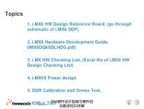
TMExternalUse1Topics1.i.MX6HWDesignReferenceBoard.(gothroughschematicofi.MX6SDP)2.i.MX6HardwareDevelopmentGuide.(IMX6DQ6SDLHDG
.pdf)3.i.MXHWCheckingList.(Excelfileofi.MX6HWDesignCheckingList)4.i.MX6XPowerdesign5.DDRCalibrationandStressTest.6.IOMuxTool1IMX硬件设计
指南与硬件启动医学知识讲解4/19/2023TMExternalUse2i.MX6HWDesignReferenceBoard.2IMX硬件设计指南与硬件启动医学知识讲解4/19/2023TMExternalUse3RelatedHardwarematerials•SABRESDP_DE
SIGNFILES.zip/SABRE_AI_DESIGNFILES.zip:SDP/AIboardschematic/layout.•IMX6DQ6SDLHDG.pdf:i.MX6Xhardwaredesignguide,includeschematic/layoutcheck
points,iomuxtools,bringup,IBIS/BSDL,RMIIinterface.•IMX6DQ/DLS_A/I/CEC.pdf:i.MX6XDatasheet:includechipsetelectricalChara
cteristicslikethevoltagerange,MaxcurrentandPowersequence.•IMX6DQ/DLS_RM.pdf:i.MX6XChipsetreferencemanual.•AN4509:i.MX6DQPowerC
onsumptionMeasurement.•AN4576:i.MX6DLSPowerConsumptionMeasurement.•IMX6_IOMUX_TOOL:iomuxconfigurationtools.•Mfgtoo
ls-Rel-4.1.0_130816_MX6Q_UPDATER.tar.gz:MFGtools.•L3.0.35_4.1.0_130816_images_MX6.tar.gz:linuxdemoimage.•HWDesignC
heckingListfori.Mx6Rev2.6.xlsx:i.MX6Xhardwarechecklist,downloadfrom:https://community.freescale.com/docs/DOC-9381
9•DDR_Stress_Tester_v1.0.3.zip:DDRtesttools,downloadfrom:https://community.freescale.com/docs/DOC-96412•i.Mx6DQSDLDDR3ScriptAid:DDRconfigura
tiontools,Downloadfrom:https://community.freescale.com/docs/DOC-94917•Freescalei.MX6DRAMPortApplicationGuid
e-DDR3https://community.freescale.com/docs/DOC-1017083IMX硬件设计指南与硬件启动医学知识讲解4/19/2023TMExternalUse4i.MX6ReferenceSolutionRelatedMaterial1.S
elect“SABREPlatformforSmartDevices”2.HardwareMaterial(Schematic,PCB,Gerber.etc);4IMX硬件设计指南与硬件启动医学知识讲解4/19/2023TMExternalU
se5SABREBoardforSmartDevices(SDB)i.MX6Quad1GhzCortex-A9Processor•Canbeconfiguredasi.MX6Dual•FreescaleMMPF0100PMIC•1GBDDR3memory(nonterminated
)•3”x7”8-layerPCBDisplayconnectors•2xLVDSconnectors•Connectorfor24bit4.3”800x480WVGAwith4-wiretouchscreen
•HDMIConnectorAudio•WolfsonAudioCodec•MicrophoneandheadphonejacksExpansionConnector•CameraCSIportsigna
ls•I2C,SSI,SPIsignalsConnectivity•2xFull-sizeSD/MMCcardslot•22-pinSATAconnector•10/100/1000Ethernetport•1xhigh-speedUSBOTG
port•mPCI-econnectorDebug•JTAGconnector•SerialtoUSBconnectorAdditionalFeatures•3-axisFreescaleaccel•eCompass•Powersupply•NobatterychargerOSSup
port•LinuxandAndroidJBfromFreescale;•Others:supportby3rdpartiesToolsSupport•Lauterbach,ARM(DS-5),Macraigordebug/IDEtoolchain
PartNumbers:MCIMX6Q-SDB($399)Display(9.7”):MCIMX-LVDS1($499)Display(4.3”):MCIMX28LCD($199)5IMX硬件设计指南与硬件启动医学知识讲解4/19/2023TMExternalUse6S
ABREPlatformforSmartDevices(SDP)i.MX6Quad1GHzCortex-A9Processori.MX6DualLite1GHzCortex-A9Processor•Freescal
eMMPF0100PMIC•1GBDDR3memory(nonterminated)•3”x7”8-layerPCBDisplayconnectors•Native1024x768LVDSdisplay(comeswith
kit)•2ndLVDSconnector•Connectorfor24bit4.3”800x480WVGAwith4-wiretouchscreen•HDMIConnector•MIPIDSIconnectorAudio•Wolf
sonAudioCodec•Microphoneandheadphonejacks•Dual1WSpeakersExpansionConnector•EnablesparallelLCDorHDMIoutput•CameraCSIportsignals•I2
C,SSI,SPIsignalsConnectivity•2xFull-sizeSD/MMCcardslot•22-pinSATAconnector•10/100/1000Ethernetport•1xhigh-speedUSBOTGport•mPCI
-econnectorDebug•JTAGconnector•SerialtoUSBconnectorAdditionalFeatures•3-axisFreescaleaccel•GPSreceiver•AmbientLightSensor•eCompass•Dual5MPCameras•P
owersupply•BatteryCharger•BatteryconnectorsOSSupport•LinuxandAndroidJBfromFreescale;•Others:supportby3rdpartiesToolsSupport•Lauterbach,AR
M(DS-5),Macraigordebug/IDEtoolchainPartNumbers:MCIMX6Q-SDP($999)MCIMX6DL-SDP($999)Display(4.3”):MCIMX28LCD($199)WiFi:SilexWiFimodule6IMX硬
件设计指南与硬件启动医学知识讲解4/19/2023TMExternalUse7SABREPlatformforAutomotiveInfotainment(AI)•PowerandMemory•FreescaleMMPF0100PMIC•2GBDDR3memory(i.M
X6Dual/Quad)•1GBDDR3memory(i.MX6Solo)•32GBParallelNORFlash•NANDSocketDisplay•LVDSconnector•compatiblewithMCIMX-LVDS1•ParallelRGBdisplayinterface•HDMI
outputconnectorDebug•JTAGconnector•DebugUARTconnectorConnectivityandExpansion•SDCardSlot•HighSpeedUSBOTG•Ether
net•SATA•MIPICSI•PCIe•MLB150INICconnector•281-pinMXMcardedgeconnectorformainboardexpansionCanbereusedfromi.MX53SABREAICo
nnectivityandExpansion•SDcardslot(WiFimoduleorSD)•BluetoothorBluetooth+WiFiheader•AM/FMtunerheader•SiriusXMModulehea
der(de-pop’’d)•GPS(UART)moduleconnector•2xCAN•DualHighSpeedUSBHostconnectors•MLB25/50INICconnector•SPINORflashDisplayI/O•LVDSconnec
tor•compatiblewithMCIMX-LVDS1•AnalogVideoInput•LVDSInputAudio•Cirrusmultichannelaudiocodec•Upto8outpu
ts•Dualmicrophoneinputs•StereoLineLevelInput•SPDIFreceiverOSSupport•Linux•Others:futuresupportby3rdpartiesCPUCardDetailsBaseBoardD
etailsPartNumbersBaseBoard:MCIMXABASEV1($699)CPUCards:MCIMX6SAICPU1($799)MCIMX6QAICPU1($799)Display:MCIMX-
LVDS1($499)7IMX硬件设计指南与硬件启动医学知识讲解4/19/2023TMExternalUse8i.MX6SMARTDEVICESYSTEMBlockDiagram8IMX硬件设计指南与硬件启动医学知识讲解4/19/2023TMExte
rnalUse9i.MX6SMARTDEVICESYSTEMSchematicHere,openi.MX6SabreSDSchematic,gothroughit.9IMX硬件设计指南与硬件启动医学知识讲解4/19/2023TMExternalUse
10i.MX6HardwareDevelopmentGuide.10IMX硬件设计指南与硬件启动医学知识讲解4/19/2023TMExternalUse11Suggestion:•Pre-design:Studythedatash
eet,powerconsumption,schematictounderstandourchipsetrequirement.•In-design:Checkthehardwaredesignguide,iomuxtools•After-design:FilltheHWde
signcheckinglist,providetheiomuxdatatosoftware.•Hardware-bringup:Checkthepower,powersequence,clock,rese
t,providethebootconfigurationtosoftware,runddrtest.•Debugport:Suggesttohave1.USBOTGPort:Forimageprog
ram,YoucanuseitasUSBhostport,noproblem.MFGjustuseUSBdevicemode.2.Debugserialport,i.MX6Xubootcanchangetosupportevery
serialportasdebugport.3.Sdcardslot:SuggesttokeepatleastoneSdcardslot,itwillhelptousetheSdcardboot,whichcanburnimagedirectl
yfromPCtoSdcard.NoneedtodebugtheMFGkernel.4.Jtag(optional).5.SuggesttousetheGPIOBoot_cfgbutnotthefuseBoot_cfg.Andbootmodepincanbepulled,becauseweca
nusethenon-imageboottoenterthedownloadmode11IMX硬件设计指南与硬件启动医学知识讲解4/19/2023TMExternalUse12i.MX6HardwareDevelopmentGuideHere,open<<IMX6DQ6S
DLHDG.pdf>>,gothroughit.1).DesignChecklist2).i.MX6SeriesLayoutRecommendations3).RequirementsforPowerManagement4
).AvoidingBoardBring-upProblems12IMX硬件设计指南与硬件启动医学知识讲解4/19/2023TMExternalUse13i.MXHWCheckingList.13IMX硬件设计指南与硬件启动医学知识讲解4/19/2023TMExt
ernalUse14i.MXHWCheckingListHere,open<<HWDesignCheckingListfori.Mx6Rev2.6.xlsx>>,gothroughit.Clear1Isvoltagelevelmatchedonbus/sign
al/logic/buffertwoside?Clear2Suggestdrawingpull-upsnearpinareawithpowerdomaindescriptioninschematic.Clear3Pleasetakecarecl
ocksourcecanmeetrequirementofperipheraldevices.(frequency/drivingcapability/jitter/tolorance/fly-timeetc.)Clear4WhenBuffer/Levelshifter/switchareus
ed,SIimpactiononsignalshouldbeconsidered.Clear5ThecontrolsignalspolarityforDirectionSellect/EN/RESETshouldbecheckedf
orallthedevices.Clear6IOconfigurationshouldbecheckedusingIOMUXToolwhichprovidedbyFreescale.Clear7The
TESTandFAULTmodeinputsoftheindividualchipsshouldbetiedtotheproperlevelfornormaloperation.Clear8Pinsequence/direction/gendersofconnectorshouldbec
onfirmedwithMechnicalconsideration.Clear9Pull-upsandvoltagesshouldbeverifiedforOC/ODsignals.Clear10Properpu
ll-upandpull-downresistorvaluesprovidedtoavoidexcesssourcingorsinkingcurrent.Clear11Thepolaritiesofthecapsanddiodesconnectedto–vevoltagesshouldbever
ified.Clear12Suggestallactivelowsignals--include“_B”atendofthesignalnetnameandallclocksignalsinclude“CL
K”aspartofnetname.Clear13Pleaseconfirmifallpowersourcehavesufficientpowercapacityandgoodenoughripplenoiselevelforrequirementofpowerinpu
t.Clear14Poweron/offsequencingshouldbeverifiedwhenmultiplepowersourcesareused.Clear15ThecurrentratingofDiode
s/Inductorsusedinthepowersupplyandotherhighcurrentsectionsshouldbeprovidedproperly.Clear16PleasepayattentiononEMI/EMC/ESD/Ligteningcons
ideration(decouplingcaps/TVSdiodes/chokes/filters/beads/fueseetc).Clear17Pleaseconfirmifunusedpinsareconfiguredproperlyfollowingformalre
commend.Clear18Pleaseconfirmbootmodeandconfigurationpinsaresetproperlyandcanmeettheactualbootrequirment.C
lear19Pleasetakecarewatchdog/cold/keyresetsystemdesign,PMICandbootdevicealsoshouldberesetatsametime.14IMX硬件设计
指南与硬件启动医学知识讲解4/19/2023TM15i.MX6XPowerdesign15IMX硬件设计指南与硬件启动医学知识讲解4/19/2023TM16i.MX6PowerRelateddoc•IMX6DQCEC.pdf:i.MX6Dual/6QuadApplicationsP
rocessorsforConsumerProducts•AN4509.pdf:i.MX6Dual/6QuadPowerConsumptionMeasurement•IMX6SDLCEC.pdf:i.MX6Solo/6DualLiteApplicationsProcessorsforConsum
erProducts•AN4576.pdf:i.MX6DualLitePowerConsumptionMeasurement•SDPschematic(PF0100):SPF-27392.pdf•Saberliteschema
tic(DiscreteDCDC)(fromboundarydevices)•IMX6DQ6SDLHDG.pdf(optional):DesignChecklist:Table2-6.Poweranddecouplerecommendatio
ns16IMX硬件设计指南与硬件启动医学知识讲解4/19/2023TM17PowerSupply,andCommonHardwareDesign17IMX硬件设计指南与硬件启动医学知识讲解4/19/20
23TM18i.MX6System-PowerDesignConsiderations•SystemPowerRequirements(oneachpowerrail)−MaxCurrentrequirement−Voltagerange•
SystemOver-VoltageProtection•PowerOnSequencing•Systemcontrolfunctions•Layout&decouple18IMX硬件设计指南与硬件启动医学知识讲
解4/19/2023TM19i.MX6PowerRailRequirements•ToFunctionproperly,thei.MX6Processorrequiresninedifferentpowerrails(Somemaybecombined)−VDDARM▪PowertoARMCo
res▪Allowedvoltage:0.9V–1.5V−VDDSOC▪VPPowertoonchipSystemPeripherals(VDDSOC_CAP):•HDMIPHY,SATAPHY,PCIEPHY,&ARMCoreCache▪PowertoImageproce
ssingmodules(VDDPU_CAP)•VPU,GPU2D,GPU3D,OpenVG▪Allowedvoltage:0.9V–1.5V19IMX硬件设计指南与硬件启动医学知识讲解4/19/2023TM20i.MX6PowerRailRequirements(co
n)−VDDHIGH▪VPHPowertoonchipSystemPeripherals(VDDHIGH_CAP)•MIPI,HDMI,SATA,PCIE,LVDS,USB,PLLs▪PowertomiscPeripherals(NVCC_PLL_OUT)•USD,PLLs,24MH
zOsc.▪SharedpowerofSNVSmodule▪Allowedvoltage:2.7V–3.3V−VSNVS▪32KHzOscillatorandSRTCfunctions▪SharedpowerofSNVSmodule▪Allowedvoltage
:2.8V–3.3V20IMX硬件设计指南与硬件启动医学知识讲解4/19/2023TM21i.MX6PowerRailRequirements(con)−USB_H1/OTG_VBUS▪PowertoUSBPHY▪Allowedvoltag
e:4.4V–5.25V−NVCC_DRAM▪PowersupplyforDRAMmemory▪Allowedvoltage:1.14V–1.575V(DependsontypeDRAM)−EthernetIOpins(NVCC_RGMII)▪All
owedvoltage:1.14–1.9V−GeneralIOpins(NVCC_)▪Typically1.8Vor3.3V▪Allowedvoltage:1.65V–3.6V21IMX硬件设计指南与硬件启动医学知识讲解4/19/2023TM22i.MX6PowerRail
Requirements-Summary•Inatypicalapplication,sixdifferentvoltagesarerequiredfortheprocessortofunction:FunctionTypica
lVoltageVDDARM,VDDSOC1.375VVDDHIGH,VSNVS3.0VUSB_VBUS5.0VNVCC_DRAM1.5VNVCC_3.3V3.3VNVCC_1.8V1.8V22IMX硬件
设计指南与硬件启动医学知识讲解4/19/2023TM23i.MX6PowerRequirements–VDDARM,VDDSOC•DatasheetMaxRequirementsforVDDARM:−3920mA•DatasheetMaxRequirementsforVDDSOC:−189
0mA•TypicalMaximumCurrentRequirements(AN4509):−Showingthreeseparatevideooutputs•1080pVideoplaybackHDMI•1080pVideoplaybackIPUPa
rallelport(LCD)•3DgraphicsthroughLVDSport▪VDDARM:1625mA▪VDDSOC:1250mA23IMX硬件设计指南与硬件启动医学知识讲解4/19/2023TM24i.MX6PowerRequirements–VDDHIGH,VSNVS•Datashe
etMaxRequirementsforVSNVS:−300uA−PullUpresistorsonVSNVSwilladdtocurrentrequirements•DatasheetMaxRequirementsforVDDHIGH:−160mA•Typica
lMaximumCurrentRequirements(AN4509):−VDDHIGH:85mA24IMX硬件设计指南与硬件启动医学知识讲解4/19/2023TM25i.MX6PowerRequirements–DRAM,IOPins•D
atasheetMaxRequirementsforDRAM:−1900mA•TypicalMaximumCurrentRequirements(AN4509):−DRAM:1390mA•DatasheetrequirementsforIOPins,use:−I(A)=NxCxVx(0.5xF)
▪N–NumberofIOpinssupplied▪C–Equivalentexternalcapacitiveload(Farads)▪V–IOvoltage(Volts)▪(0.5xF)–Datachangerate,whereF=Frequency(Hz
)−Typical=2-3mAfora3.3Vpin25IMX硬件设计指南与硬件启动医学知识讲解4/19/2023TM26SummaryPowerRequirementsPowerRailVoltageTypicalMaximumVDDARM1.375V1625mA3920mAV
DDSOC1.375V1250mA1890mAVDDHIGH2.8V85mA160mAVSNVS3.0V-300uADRAM1.5V1390mA1900mAUSB5.0V500mA530mAI/OPins3.3V300mA500mA*I/OPins1.8V50mA275mA**Maximumval
uesaremutuallyexclusive26IMX硬件设计指南与硬件启动医学知识讲解4/19/2023TM27TypicalConsumerDevicePowerRequirementsFunctionVoltageTypicalMaximumSDCard3.3V100mAW
IFI/BT3.3V1000mA3G/4GModem3.3V2000mA3000mALVDS3.3/5V300/370mAHDMI5V50mAEthernet3.3V130mAAudio1.8/5V40/100mA80/530mASATA5V500-1000mA1500mAeMMC3.3V100
mA200mACAN5V70mAGPS1.5/3.3V20/100mACamera1.5/1.8V150/20mA27IMX硬件设计指南与硬件启动医学知识讲解4/19/2023TM28GrandTot
alPowerRequirementsVoltageTypicalFullPower1.375V1875mA5800mA1.5V1500mA2300mA1.8V100mA350mA3.0V160mA200mA3.3V2000mA5000mA5.0V1500mA3300mA28IMX
硬件设计指南与硬件启动医学知识讲解4/19/2023TM29i.MX6System-PowerDesignConsiderations•TotalSystemPowerRequirements−TypicalSystemrequirement
s(5Vsource):2.9A−TypicalSystemrequirements(3.7Vsource):4.1A•SystemOver-VoltageProtection▪SelectPowercomponentswithhighvoltagetolerance▪De
signOver-Voltageprotectionsub-system▪Userbatterychargingcircuitwithprotection.•PowerOnSequencing•Systemcontrolfun
ctions−Stand-by,reducedpoweroptions29IMX硬件设计指南与硬件启动医学知识讲解4/19/2023TM30i.MX6System-PowerOn/OffSequencing•PowerOnSequencing1.VDD
_SNVS_IN=<VDDHIGH_IN<anyotherpowersupply(FSLsuggestVDDHIGN_INpowerwithVDD_SNVS_INorinstep2)2.VDDARM_IN<=(V
DDSOC_IN-1ms);Vvddarm_cap<=(Vvddsoc_cap+50mV):IfVDDARM_INandVDDSOC_INareconnectedtodifferentexternalsupplysources•PowerOffSequencingN/A•Notes:
1.Needtoensurethatthereisnobackvoltage(leakage)fromanysupplyontheboardtowardsthe3.3Vsupply(forexample,fro
mtheexternalcomponentsthatusebthth18Vd33Vli)30IMX硬件设计指南与硬件启动医学知识讲解4/19/2023TM31IMX6DQ6SDLHDG:Table2-6.P
oweranddecouplerecommendations•VGEN5forVDDHIGH_INandincreaseto3Vtoalignwithdatasheet•Onlyone22μFbulkcapacitorshouldbeconne
ctedtoeachoftheseon-chipLDOregulatoroutputs:VDD_ARM/23/SOC/PU_CAPasnearaspossiblewithpins/vias.Thedistanceshouldbele
ssthan50milbetweenbulkcapandVDD_xx_CAPpins;ripplenoiseshouldbelessthan5%Vp-pofsupplyvoltageaverageval
ue•NVCC_LVDS2P5mustbepowered-onevenwhennotusingtheLVDSinterfacebecauseTheDDRpre-driverssharetheNVCC_LVDS2P5powerrailwiththe
LVDSinterface31IMX硬件设计指南与硬件启动医学知识讲解4/19/2023TM3232i.MX6Dual/Quad:5vINPUT+PFUSE100:SDPIMX硬件设计指南与硬件启动医学知识讲解4/19/2023T
M3333i.MX6Dual/Quad:5vDiscretePowerIMX硬件设计指南与硬件启动医学知识讲解4/19/2023TM34DevelopToolsDDRStressTest34IMX硬件设计指
南与硬件启动医学知识讲解4/19/2023TM35DDRStressTestTool•WhatisDDRStressTesterkit?Itisdownloadabletestapplicationarchitecture.Aprogramrunni
ngonPC(DDR_Stress_Tester.exe,whichrunningonCommandPromptwindow)willdownloadthetestimagetotargetboard’sIRAMwiththe
helpofUART/USBconnection.ThetestimagewilldotheDDRstresstestandtheresultwillbesenttoPCthroughUART/USBandbeprintedontheCommandPromptwindow.•Form
x6dq,mx6dlsormx6sl,UARTisnotsupported.•Supportmx53,mx51,mx6dq,mx6dlsandmx6sl.35IMX硬件设计指南与硬件启动医学知识讲解4/19/2023TM36DDRStressTest
Toolcont.TestLogLink36IMX硬件设计指南与硬件启动医学知识讲解4/19/2023TM37DevelopToolsIOMuxTool37IMX硬件设计指南与硬件启动医学知识讲解4/19/2023TM38IOMUXTool•ApplicationWindowOvervie
w38IMX硬件设计指南与硬件启动医学知识讲解4/19/2023TM39DownloadandInstalltheMicrosoft.NETFramework4.0•http://msdn.microsoft.com/en-us/netframew
ork/aa56926339IMX硬件设计指南与硬件启动医学知识讲解4/19/2023TM40SelectModulesandSignalsforBoard•ChecktheUARTS:UART1,UART2andUART3.•Expandallsignalsu
nderUART3.40IMX硬件设计指南与硬件启动医学知识讲解4/19/2023TM41AccessingMuxed-SignalInfo41IMX硬件设计指南与硬件启动医学知识讲解4/19/2023TM42AccessingMuxed-SignalInfo42IMX硬件设计指南与
硬件启动医学知识讲解4/19/2023TM43ResolveConflictingSignalsSelectALT4–EIM_D30(J20)forUART3/CTS.SelectALT4–EIM_D3
1(H21)forUART3/RTS.SelectALT2–SD4_CLK(E16)forUART3/RXD_MUX.SelectALT2–SD4_CMD(B17)forUART3/TXD_MUX.43IMX硬件设计指
南与硬件启动医学知识讲解4/19/2023TM44AddingCommentsforClarity•Right-clicktheUART2/TXD_MUXrowintheSignalstabtobringupthecontextmenu.•Clickingonthemenuwill
bringupatextentryfieldwheretheusermayentertext.44IMX硬件设计指南与硬件启动医学知识讲解4/19/2023TM45AddingCommentsforClar
ity45IMX硬件设计指南与硬件启动医学知识讲解4/19/2023TM46BallDiagramView46IMX硬件设计指南与硬件启动医学知识讲解4/19/2023TM47Pads“Spreadsheet”View47IMX硬件设计指南与硬件启动医学知识讲解4/
19/2023TM48ConfiguringIOMUXCRegisters•SelectUART3/RXD_MUXintheleft-handpane.•AlloftheIOMUXCRegistersassociatedwiththeAD4_CLK(E16)padareshow
nontheRegistersTabintheright-handpane.48IMX硬件设计指南与硬件启动医学知识讲解4/19/2023TM49DragaSignaltoanotherModule49IMX硬件设计指南与硬件启动医学知识讲解4/19/2023TM50Rename
SignaltoMatchSchematics50IMX硬件设计指南与硬件启动医学知识讲解4/19/2023TM51CAN1ModulewithAllSignals•Commentsauto-generatedtodenoteoriginalModule/S
ignal.51IMX硬件设计指南与硬件启动医学知识讲解4/19/2023TM52CodeReflectsAddedSignals•BasicCodeStyleasaTooltip.52IMX硬件设计指南与硬件启动医学知识讲解4/19
/2023TM53GenerateConfigurationCode•SeveralCode-StylesavailableintheCodeMenu.•ExamplesareshownintheUser’sGuide.•Click“G
enerateCode”tocreatethefilesforthecurrentdesign.Tryit53IMX硬件设计指南与硬件启动医学知识讲解4/19/2023TM54i.MX6XHardwarebringup54IMX硬件设计指南与
硬件启动医学知识讲解4/19/2023TM55i.MX6XHardwarebringup:Doc&Tools.•IMX6DQ6SDLHDG.pdf:Chapter8AvoidingBoardBring-upProblems.•IMX6XRM.pdf:Chapter7SystemBoot,Cha
pter60:SystemResetController(SRC)•MFGtools,DDRtesttools.•USBline;有源可限流电源,万用表,示波器55IMX硬件设计指南与硬件启动医学知识讲解4/19/2023T
M56i.MX6XHardwarebringup:Step1目视检查•检查主要器件是否有错贴的情况,比如说二极管,三极管,有没有安装位置反向或旋转的问题。•可以在PCBA时使用X光检查,有条件的使用BSDL检查来确认焊接与连线56IMX硬件设计指南与硬件启动医学
知识讲解4/19/2023TM57i.MX6XHardwarebringup:Step2电源检查•使用万用表,先空板检查每个电源有没有对地短路的情况。•使用限流电源上电,检查i.MX6X每路电源的电压是否符合
我们datasheet要求,量测电压是要求在电源输出端和i.MX6X电源输入端(越近越好,如在滤波电容上量测)都量测一下,以避免IR跌落。VDD_ARM/SOC_IN供给i.MX6X内部逻辑电路,需要仔细检查,VDD_SNVS_IN,NVCC_JTAG
,NVCC_DRAM也对正常启动很重要,NVCC_LVDS2V5也供给了DDRI/OPads,也必须要正常供给。•i.MX6X在各路电源稳定后,才能释放reset(POR_B)。•如前电源上电时序要求,检查上电时序。57IMX硬件设计指南与硬件启动医学知
识讲解4/19/2023TM58i.MX6XHardwarebringup:Step3时钟检查•一般在电源电压正确,无跌落,24Mhz和32K晶体会自动起振。•可使用示波器量测这两个时钟,如果24Mhz不工作,则系统不能启动,如果外部没有32K,或32K不工作,则i.MX6
X会自动使用内部晶振,但根据newerrataIM6DQCERev.4,07/2014:ERR007926ROM:32kHzinternaloscillatortiminginaccuracymayaffectSD/MMC,NAND,andOneNANDboot,由于内部r
omcode的GPT使用这个时钟,而GPT被用于外设访问中一些event和timeout控制,所以不稳定的时钟有可能导致romcodes读取外设失败,所以建议连接外部32K.58IMX硬件设计指南与硬件启动医学知识讲解4/19/2023TM59i.MX6XHardwar
ebringup:Step4准备bringup文档一般硬件工程师需要准备三份文档描述板级设计•电源文档:每一路电源的源,供给到?输出,输入电压,测量点,时序。如SDPschematic:59IMX硬件设计指南与硬件启动医学知
识讲解4/19/2023TM60i.MX6XHardwarebringup:Step4准备bringup文档•IOMUX文档:可以使用iomux工具导出,也可以手动准备,内容最好包括:以方便软件工程师配置IOMUX,这个表应该至少包括所有数字管脚,软件工程师根据这个表来配置i
omux文件:arch\arm\mach-mx6\Board-mx6q_sabersd.hstaticiomux_v3_cfg_tmx6q_sabresd_pads[]={…/*UART1fordebug*/MX6Q_PAD_CSI0_DAT10__UART1_TXD,//CS
I0_DAT10为管脚名,UART1_TX会功能名。Notes:1i.MX6X基本所有的可做为GPIO的pin在reset状态下都是iomux设为gpio,gpio设为输入高阻,iopad设为100K上拉的.2i.MX6X的datasheet中也列出了
一些例外:Formostofthesignals,thestateduringresetissameasthestateafterreset,However,therearefewsignalsforwhichthestatedu
ringresetisdifferentfromthestateafterreset:EIM_A16~A25,EIM_DA0~DA15,EIM_EB1~EB3,EIM_LBA/RW/WAIT,GPIO_17/19,KEY_COL0,请注意有一些pin是用于bootgpio的.管脚名脚管序号网络名
IOMUX用于CSI0_DATA10M1UART1_TXALT3UART1_TX60IMX硬件设计指南与硬件启动医学知识讲解4/19/2023TM61i.MX6XHardwarebringup:Step4准备bringup文档•Boot_Cfg文档:说明
Boot_cfg配置,以SDP的eMMCboot为例FuseSBMR1定义GPIO管脚默认值设置值默认值定义BOOT_CFG1[7:6]Bit7_6启动设备接口EIM_DA7_6000101:BootfromUSDHCBOOT_CFG1[
5]bit5SD/MMCSelEIM_DA5010:SD/eSD/SDXC;1:MMC/eMMCBOOT_CFG1[4]bit4FastBootSuppoEIM_DA4000:NormalBoot;1:FastBootB
OOT_CFG1[3:2]bit3_2SD/MMC速度模式EIM_DA3_20000MMC:0x:HighSpeedMode;1x:NormalSpeedModeSD:0x:High/Normal;10:SDR50
;11:SDR104BOOT_CFG1[1]bit1SDPowerCycleeMMCResetEIM_DA100MMC:0:eMMCresetdisabled.1:eMMCresetenabledviaSD_RSTpad(onUSDHC3/4)SD:0:Nopowercycle1:Power
cycleenabledvisSD_RSTpad(onUSDHC3/4)BOOT_CFG1[0]bit0SDLoopbackClockSourceSel(SDR50/104only)EIM_DA0000:th
roughSDpad1:directBOOT_CFG2[7:5]bit15_13BusWidth/SDCalibrationStepEIM_DA15~13000010SD:BusWidth:xx0:1bit;xx1:4
bit.SDCalibrationStep:00x~11x:1~3delaycellsMMC000~010:1,4,8bit.101~110:4,8bitDDR(MMC4.4)61IMX硬件设计指南与硬件启动医学知识讲解4/19/2023TM
62i.MX6XHardwarebringup:Step4准备bringup文档SDP的BootSelect为:所以eMMC启动的SBMR1=0Xxxx5860FuseSBMR1定义GPIO管脚默认值设置值默认值定义BOOT_CFG2[4:3
]Bit12_11启动设备接口EIM_DA12_11001100~11:USDHC1~4BOOT_CFG2[2]Bit10DLLOverride(eMMC)EIM_DA10000:BootROMdefault;1
:ApplyvalueperfuseMMC_DLL_DLY[6:0]BOOT_CFG2[1]Bit9BootACKdisable/PulldownDuringPowerCycleEnableEIM_DA900MMC:0:BootACKEnabled;1:BootACKDisabled.S
D:0:UsethedefaultSDpadsettingsduringpowercycle.1:SetPulldownonSDpadsduringpowercycleBOOT_CFG2[0]bit8OverridePadSettingsEIM_DA8000:
Usethedefaultvalues.1:UsePAD_SETTINGSvalues.62IMX硬件设计指南与硬件启动医学知识讲解4/19/2023TM63i.MX6XHardwarebringup:Step5确认启动配
置i.MX6X在上电正确,时钟正确,POR正确后,会首先执行内部的ROMcodes,这个ROMcodes,首先会读取SBMR2寄存器的值,来判断启动模式,如果为下载模式,则进入下载模式。如果为正常启动模式则
会根据读取SBMR1寄存器的值来初始化相应启动设备的控制器,并尝试去读取相应设备上的镜像,并认证。如果认证成功,则根据镜像开头的数据结构来初始化外部DDR,然后将镜像拷贝到外存,并跳转到外存执行bootloader。如果镜像认证失败,则又进入下载模式。进入下载模式后,i.
MX6X会通过USBOTG口与hostPC联系,并报告为一个HID设备。所以从PC上可以看到一个USBHID设备信息。如果有这个信息报出,证明i.MX6X的最小系统工作了(电源,时钟,POR,内部ROMcodes已经执行并进入了下载模式)。如果我们已经设置为正常
启动模式,并且配置boot_cfg相应的GPIO,则可以使用示波器量测启动设备上相应的时钟:•Nand:CEpinforreadenableclock•SPI-NOR:SlaveSelectorClockpin.•
MMC/SD:SD_CLKpin.如果有时钟,则说明ROMcodes已经开始读取相应启动设备,硬件Boot_cfgGPIO配置是正确的。如果没有,则说明Boot_cfgGPIO配置可能有问题,需要再次检查硬件。63IMX硬件设计指南与硬件启动医学知识讲解4/19/2
023TM64i.MX6XHardwarebringup:Step6测试外部内存i.MX6X最小系统工作以后,下一步需要保证外部内存已经工作了,这样才可以确保bootloader软件可以工作。所以接下来需要测试外部DDR.•根据DDRdatasheet,使用Mx6DQSDLDDR3S
criptAid工具来生成DDR初始化脚本。•连接硬件,运行DDR_Stress_Tester.exe•–tmx6x–dfMX6QD_SabreSD_DDR3_528MHz_64bit.inc,根据提示来校准DDR及进行压力
测试。如果压力测试通过,则说明外部DDR工作正常。•DDR测试详细请参看文档MX6X_DDR3_调校_应用手册_V1.doc•DDR初始化脚本可作为bootloader中的DDR初始化数据结构用,在文件:uboot\boar
d\freescale\mx6q_sabersd\flash_header.s•使用\u-boot-2009.08\include\configs\mx6q_sabresd_iram.h可以编译出基于内部
iRam运行的uboot,对比运行在外部DDR的uboot可以判断是否为外部DDR问题。64IMX硬件设计指南与硬件启动医学知识讲解4/19/2023TM65i.MX6XHardwarebringup:完成以上步骤完成后,则可以初步说明i.MX6X系统(i.MX6X,电源,外部DDR)工
作正常。可以进行接下来的软件bringup工作。软件定制基本包括:•根据DDR初始化脚本来配置uboot的flash_header数据结构。•根据IOMUX文档来配置uboot和内核的iomux数组。•根据板级的外设情况来准备一个相对较小的内核,并编译出MFG和正常内
核。•使用MFG烧写启动设备,调试MFG内核。•烧写成功后,启动,如果有uboot串口消息打出,则可以使用串口消息来继续调试。65IMX硬件设计指南与硬件启动医学知识讲解4/19/2023TM66i.MX6XHardwarebringup:一些调试方法1:确认启动
配置刚才说到可以通过量测启动设备相应的管脚clock信号来判断Boot_cfg设置是否正确,而如果MFG及MFG镜像可以工作,也可以使用MFG直接读取SBMR1寄存器来获取:1.将MFG的uboot换成正常启动的uboot,即替换掉\Mfgtools-Rel-4.1
.0_130816_MX6Q_UPDATER\Profiles\MX6QLinuxUpdate\OSFirmware\u-boot-mx6q-sabresd.bin(MFG的uboot和正常启动的uboot
对比一个不同就是MFG的uboot取消了等待3S输入的功能,而正常的uboot可以)2.启动板子,进入下载模式(bootmode为下载,或是启动镜像认证失败都会进入)。3.进入下载模式后就可以运行MFG,将正常启动的uboot镜像下载到外部内存并运行起来。4.在串口上键入“空格”,停下ubo
ot,然后使用uboot的”md”命令就可以读取sbmr1寄存器:”md020d8004”(sbmr1寄存器地址),在SDP,eMMC启动时为0x00005860,与上文我们配置的一致。所以总结下来如果系统因为启动模式不对而进入到下载模式,我们可以通过MFG来精确确认SBMR1寄存器值,从
而了解是那些Boot_CfgGPIO配置不对。66IMX硬件设计指南与硬件启动医学知识讲解4/19/2023TM©2014FreescaleSemiconductor,Inc.|ExternalUsewww.Freescale.com67IMX硬件设计指南与硬件启动医学知识讲解
4/19/2023
 辽公网安备 21102102000191号
 营业执照
营业执照